The Bias voltages
Basically I don't need any bias for a class E amp. But I wanted to build the bias for experimenting with several aspects of an amp.
What is the max output without and with bias ? Wat is the efficiency with different biases ? What about the linearity of the amp, etc. ? So, a bias it will be in the first prototype. It is not difficult, but it takes quite some components to make two bias circuits for two FET's. The most important property of a bias should be:
- stone cold DC, no unwanted feed back on the gates
- no influence of the power supply on the bias voltage
- max about 4.2 Volt, in order to reach the FETs opening voltage.
Well, it is not very difficult, just put it together,......
Some further comments:
- I used a little spreadsheet to calculate the output voltage if you turn on the multi potmeter.
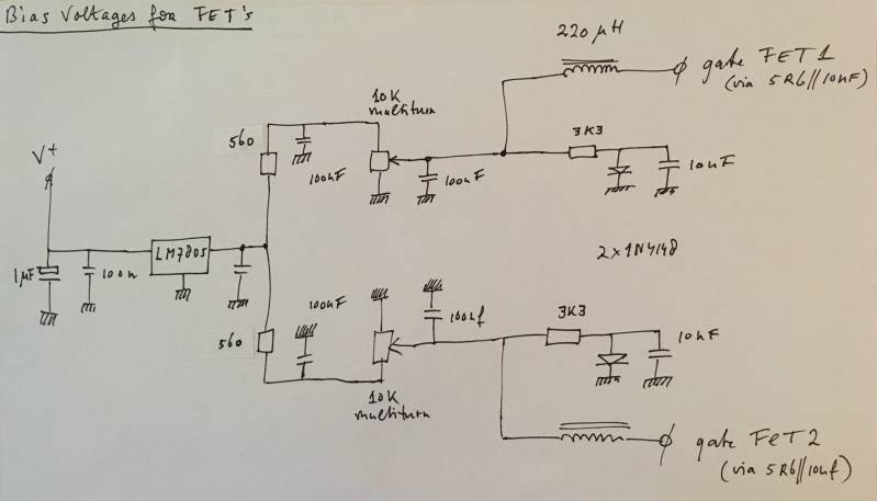
- The diode in the circuit makes the curve a little more flat in the middle, so the sensitivity is lower. Easier to precisely set up the bias voltage.
- I personally use 4 diodes in series instead of 1, and I lowered the 560 ohm resistor to 390, and the 3k3 resistor to 1500 ohm. The result is an even flatter curve, with a steeper start until 2-2.5 volt. The Vmax here is about 4.4 Volt. In practice we will see how it works and can make changes if necessary.
- The 220 uH inductance has to keep the fr away from the bias voltage.
Create Your Own Website With JouwWeb